|
PETRA CAVITY ROOMS and
PETRA VERTICAL tunnel to the resonant chamber and discovery of MAGNETRON.
Discovery by Rudolf Bosnjak
To comprehend and understand my research work and my research explanations and my drawings you must be sound engineer or electronic engineer not archeologist. Explanations here are totally opposite from science of archeology.
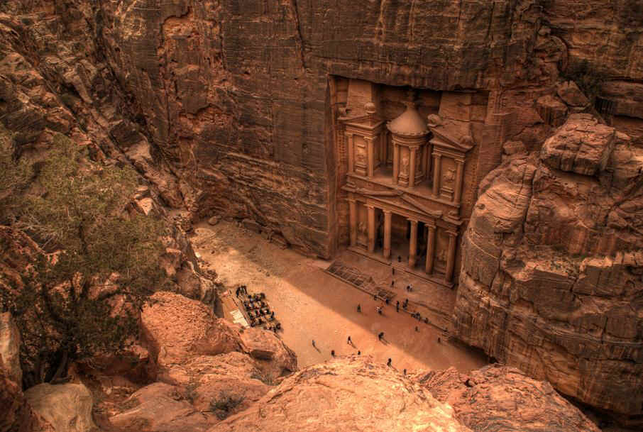
Below image show what disappear in front of PETRA door.
Humans usually call this circular shape as TEMPLE but this shape has very specific purpose and if you read my research work and accept my discoveries I hope will comprehend and understand, if not you will still believe archeologist and fake explanation about knowledge of Nabatean people. Regards Rudolf Boschnjak) Bosnjak
Prava kopiranja ©. 2015. Sva prava pridržana. Rudolf Bošnjak. Copyright ©. 2015 All rights reserved. Rudolf (Boschnjak) Bosnjak.

Is this huge magnetron...
Prava kopiranja ©. 2015. Sva prava pridržana. Rudolf Bošnjak. Copyright ©. 2015 All rights reserved. Rudolf (Boschnjak) Bosnjak.
Prava kopiranja ©. 2015. Sva prava pridržana. Rudolf Bošnjak. Copyright ©. 2015 All rights reserved. Rudolf (Boschnjak) Bosnjak.
Prava kopiranja ©. 2015. Sva prava pridržana. Rudolf Bošnjak. Copyright ©. 2015 All rights reserved. Rudolf (Boschnjak) Bosnjak.

Prava kopiranja ©. 2015. Sva prava pridržana. Rudolf Bošnjak. Copyright ©. 2015 All rights reserved. Rudolf (Boschnjak) Bosnjak.
Petra complex is huge magnetron...
Construction and working of Magnetron to comprehend and understand
please go to read full article and information and come back after reading.This is image visible every where, all line in RED, line in GREEN you can see them in all Buddhist, Hindu and Jews temples and orthodox and catholic churches and in all Islam Muslim mosque and is always told to humans as those lines represent: god, lord, and Allah. Now for the first time you have opportunity to comprehend and understand what is religion telling and what is electronic explanation for those lines and magnetic lines and electric lines and their movement.

RED LINE IN EPITROCHOID MOVEMENT
SHAPE IN MAGNETRON IS SECRET
OF FOUR RABBIT,
AND TO COMPREHEND AND UNDERSTAND WHAT IS FOUR RABBIT GO AND READ MY
RESEARCH HERE.
This drawing explains all religious lies and scams of all religions that exist on planet earth for thousands of years and all the ignorance of all spiritual and spritualnih teachers, pastors, priests, bishops, popes, imams, mufti and all other religious liars, who do not know to explain nothing about it that they say and assure human sheep all these centuries that god, allah has but do not know that it draw. Here is a drawing of a god or allah, but as a magnetron.
Prava kopiranja ©. 2015. Sva prava pridržana. Rudolf Bošnjak. Copyright ©. 2015 All rights reserved. Rudolf (Boschnjak) Bosnjak.
Prava kopiranja ©. 2015. Sva prava pridržana. Rudolf Bošnjak. Copyright ©. 2015 All rights reserved. Rudolf (Boschnjak) Bosnjak.

Prava kopiranja ©. 2015. Sva prava pridržana. Rudolf Bošnjak. Copyright ©. 2015 All rights reserved. Rudolf (Boschnjak) Bosnjak.


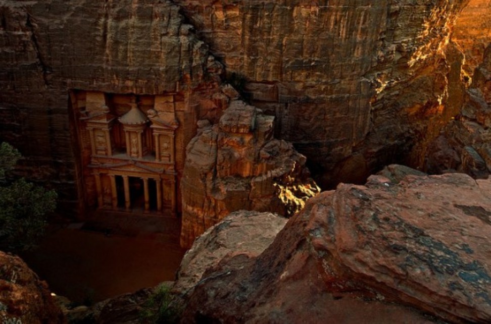
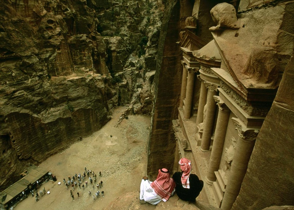
The Treasury Al Khazna, location Petra, Wadi Musa, Jordan.
Prava kopiranja ©. 2015. Sva prava pridržana. Rudolf Bošnjak. Copyright ©. 2015 All rights reserved. Rudolf (Boschnjak) Bosnjak.
PETRA CAVITY ROOM FROM VERANDAH


PETRA - THIS IS MAIN VERANDAH ENTRANCE, LEFT and RIGHT SIDE.
There is doors to left side room space I call V4 and dooors to right side room I call V5.
Prava kopiranja ©. 2015. Sva prava pridržana. Rudolf Bošnjak. Copyright ©. 2015 All rights reserved. Rudolf (Boschnjak) Bosnjak.
HERE IS MY ATTEMPT TO EXPLAIN PETRA MAIN VERANDAH TO COMPREHEND AND UNDERSTAND WHAT IT IS: Whip delay line meander. It is same in shape and form as MAIN VERANDAH IN PETRA ENTRANCE, has doors to left side room I call V4 and has doors to right side room I call V5.

MAIN VERANDAH IN PETRA ENTRANCE IS ACTUALLY WHIP DELAY LINE, AS OLD GREEK PEOPLE CALL MEANDER. When compare PETRA MAIN VERANDAH and I call PILLARS DELAY LINE (meander) I come to same conclusion that BOTH PARTS are same device, but from much bigger device...
A meander, in general, is a bend in a sinuous watercourse or river. A meander forms when moving water in a stream erodes the outer banks and widens its valley, and the inner part of the river has less energy and deposits silt.
In reality this is kind of microwave device and can be used to convert electric current into electromagnetic waves. In basic this is a detailed (or linear) magnetron.
Only problem appear that PETRA MAGNETRON IS SO HUGE in dimensions and wavelength can not be in microwave frequencies.What was frequencies used in PETRA MAGNETRON is still part of my research, so in bottom text I write.
To comprehend and understand this PETRA - Ultra-Wide Band Multifunction Antennas, please go to read full article and information and come back after reading.
Prava kopiranja ©. 2015. Sva prava pridržana. Rudolf Bošnjak. Copyright ©. 2015 All rights reserved. Rudolf (Boschnjak) Bosnjak.

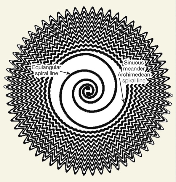
Classic sinuous shape with linear growing rate τ (right) sinuous shape with meandering (informally called zig zag sinuous).
Below is few images showing what was PETRA - Ultra-Wide Band Multifunction Antennas and this carved drawing is in Christian religion false explanation as ALTAR...
Many years I spent do decipher this Marble altar detail on Abbey of Sant Pietro image and all explanation from carving text and translation was wrong until I come to comprehend and understand what is Ultra-Wide Band Multifunction Antenna, because this was explanation for this drawing.
BUT, WHAT I DISCOVER 6 MARCH 2015 IS THAT WHAT IS SHOWN HERE IS TRULY AND ACTUALLY EXPLANATION HOW WORKING MAGNETRON. IT IS FULL DRAWING AND PRINCIPE HOW WORKING MAGNETRON IN DIFFERENT PHASES OF WORKING STATES WITH FULL DETAILS.
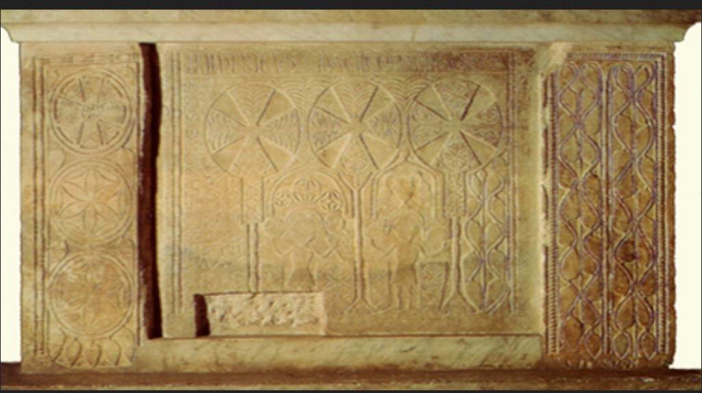

PETRA - Marble altar detail Abbey of Sant Pietro in Valle Ferentillo 1996 Florence Italy. Christian religion false explanation as ALTAR...OLTAR.
BUT, WHAT I DISCOVER 6 MARCH 2015 IS THAT WHAT IS SHOWN HERE IS TRULY AND ACTUALLY EXPLANATION HOW WORKING MAGNETRON. IT IS FULL DRAWING AND PRINCIPE HOW WORKING MAGNETRON IN DIFFERENT PHASES OF WORKING STATES WITH FULL DETAILS.
Prava kopiranja ©. 2015. Sva prava pridržana. Rudolf Bošnjak. Copyright ©. 2015 All rights reserved. Rudolf (Boschnjak) Bosnjak.
PILLARS DELAY LINE IN MEANDER
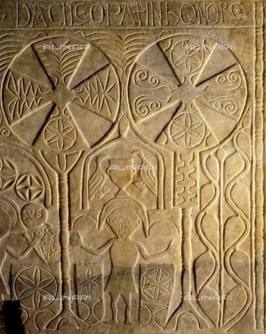

Many years I spent do decipher this Marble altar detail on Abbey of Sant Pietro image and all explanation from carving text and translation was wrong until I come to comprehend and understand what is Ultra-Wide Band Multifunction Antenna, because this was explanation for this drawing.
BUT, WHAT I DISCOVER 6 MARCH 2015 IS THAT WHAT IS SHOWN HERE IS TRULY AND ACTUALLY EXPLANATION HOW WORKING MAGNETRON. IT IS FULL DRAWING AND PRINCIPE HOW WORKING MAGNETRON IN DIFFERENT PHASES OF WORKING STATES WITH FULL DETAILS.
Classic shape with linear growing rate visible from Lombard Christian altar as meandering (informally called zig zag sinuous). Christian religion false explanation as ALTAR...
Prava kopiranja ©. 2015. Sva prava pridržana. Rudolf Bošnjak. Copyright ©. 2015 All rights reserved. Rudolf (Boschnjak) Bosnjak.
BUT, WHAT I DISCOVER 6 MARCH 2015 IS THAT WHAT IS SHOWN HERE IS TRULY AND ACTUALLY EXPLANATION HOW WORKING MAGNETRON. IT IS FULL DRAWING AND PRINCIPE HOW WORKING MAGNETRON IN DIFFERENT PHASES OF WORKING STATES WITH FULL DETAILS.
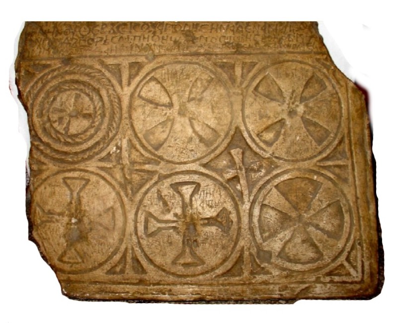
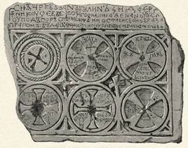
Many years I spent do decipher this Ban Kulin board image and all explanation from carving text and translation was wrong until I come to comprehend and understand what is Ultra-Wide Band Multifunction Antenna, because this is only explanation for this drawing.
Classic shape with linear growing rate visible from as meandering (informally called zig zag sinuous).
BUT, WHAT I DISCOVER 6 MARCH 2015 IS THAT WHAT IS SHOWN HERE IS TRULY AND ACTUALLY EXPLANATION HOW WORKING MAGNETRON. IT IS FULL DRAWING AND PRINCIPE HOW WORKING MAGNETRON IN DIFFERENT PHASES OF WORKING STATES WITH FULL DETAILS.
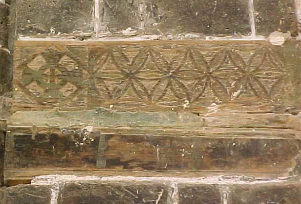
EXTERIOR WALL OF COPTIC CHURCH MOHARRAK.
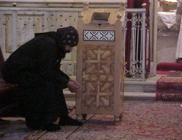
Deir Al Moharrak BOX
BUT, WHAT I DISCOVER 6 MARCH 2015 IS THAT WHAT IS SHOWN HERE IS TRULY AND ACTUALLY EXPLANATION HOW WORKING MAGNETRON. IT IS FULL DRAWING AND PRINCIPE HOW WORKING MAGNETRON IN DIFFERENT PHASES OF WORKING STATES WITH FULL DETAILS.
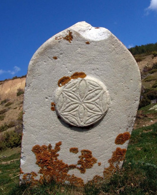
Many years I spent do decipher this image from STECHAK BORJE, ALBANIJA and all explanation from carving text and translation was wrong until I come to comprehend and understand what is Ultra-Wide Band Multifunction Antenna, because this is only explanation for this drawing.
BUT, WHAT I DISCOVER 6 MARCH 2015 IS THAT WHAT IS SHOWN HERE IS TRULY AND ACTUALLY EXPLANATION HOW WORKING MAGNETRON. IT IS FULL DRAWING AND PRINCIPE HOW WORKING MAGNETRON IN DIFFERENT PHASES OF WORKING STATES WITH FULL DETAILS.
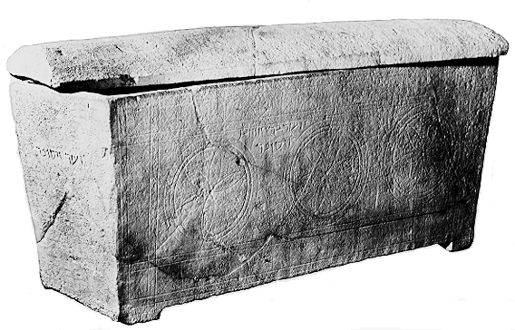
Ossuary from Jifna Jordan 70A.D.
Many years I spent do decipher this image from Ossuary from Jifna Jordan 70A.D. and all explanation from carving text and translation was wrong until I come to comprehend and understand what is Ultra-Wide Band Multifunction Antenna, because this is only explanation for this drawing.
BUT, WHAT I DISCOVER 6 MARCH 2015 IS THAT WHAT IS SHOWN HERE IS TRULY AND ACTUALLY EXPLANATION HOW WORKING MAGNETRON. IT IS FULL DRAWING AND PRINCIPE HOW WORKING MAGNETRON IN DIFFERENT PHASES OF WORKING STATES WITH FULL DETAILS.
NOW SEE SAME RADIATION PATTERNS FROM BOSNIA STECHAK
BUT, WHAT I DISCOVER 6 MARCH 2015 IS THAT WHAT IS SHOWN HERE IS TRULY AND ACTUALLY EXPLANATION HOW WORKING MAGNETRON. IT IS FULL DRAWING AND PRINCIPE HOW WORKING MAGNETRON IN DIFFERENT PHASES OF WORKING STATES WITH FULL DETAILS.

Many years I spent do decipher this image from stechak from Gornja Zgoscha, Bosnia and all explanation from carving text and translation was wrong until I come to comprehend and understand what is Ultra-Wide Band Multifunction Antenna, because this is only explanation for this drawing.
BUT, WHAT I DISCOVER 6 MARCH 2015 IS THAT WHAT IS SHOWN HERE IS TRULY AND ACTUALLY EXPLANATION HOW WORKING MAGNETRON. IT IS FULL DRAWING AND PRINCIPE HOW WORKING MAGNETRON IN DIFFERENT PHASES OF WORKING STATES WITH FULL DETAILS.
PETRA - PILLARS DELAY LINE IN MEANDER WAVEFORM IN ROTATION
Prava kopiranja ©. 2015. Sva prava pridržana. Rudolf Bošnjak. Copyright ©. 2015 All rights reserved. Rudolf (Boschnjak) Bosnjak.
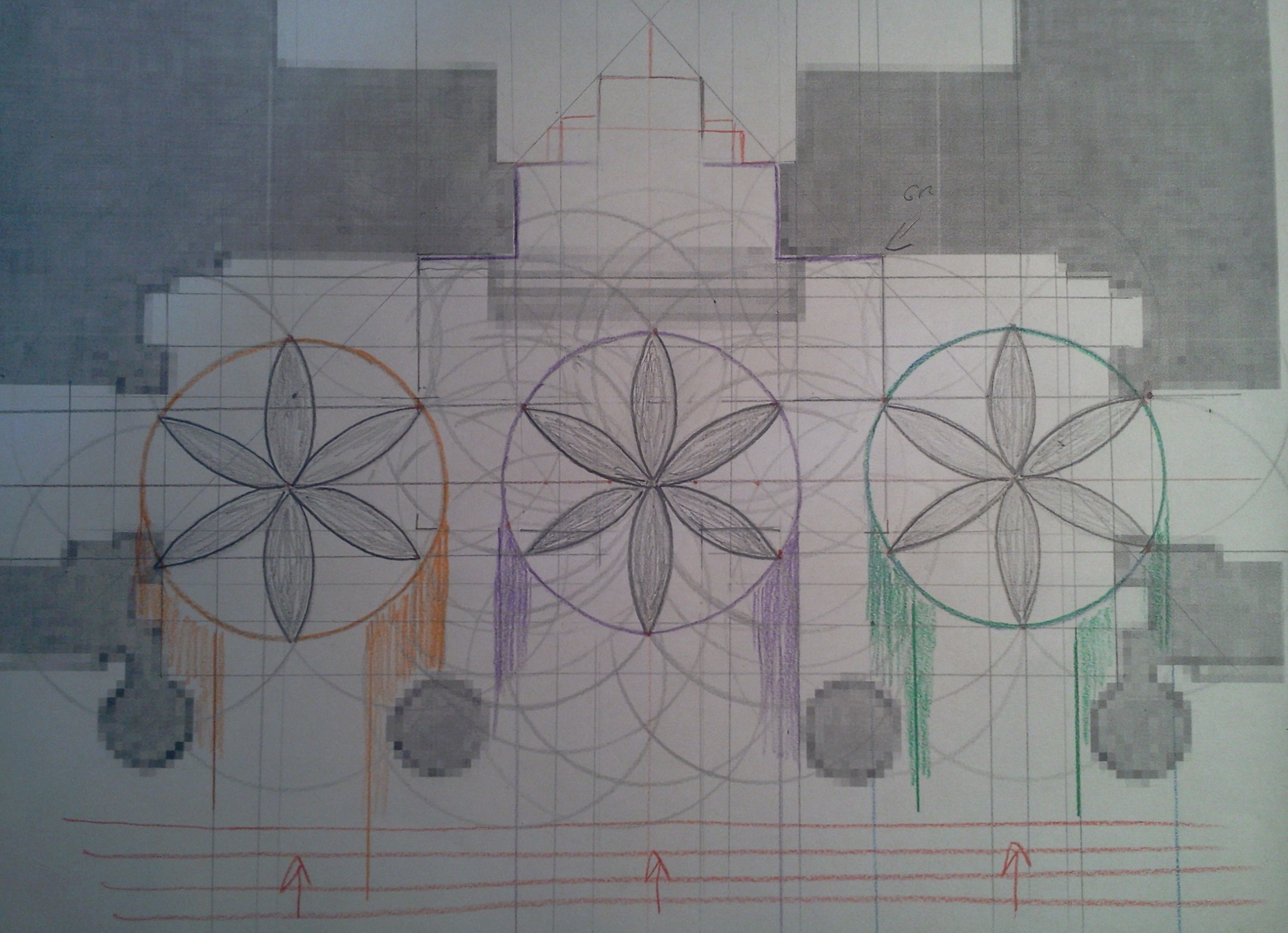
This is my hand drawing what was happening in ANCIENT PAST TIME IN PETRA MEANDER SPACE PILLARS DELAY LINE when RECEIVE RADIATION PATTERN I MARK WITH RED ARROWS and ENTER BETWEEN PILLARS DELAY LINE INTO VERANDAH from Ultra Wide Band Multifunction Antenna in Figure 2.
Prava kopiranja ©. 2015. Sva prava pridržana. Rudolf Bošnjak. Copyright ©. 2015 All rights reserved. Rudolf (Boschnjak) Bosnjak.

RADIATION PATTERN IS SENT FROM CONICAL Ultra Wide Band Multifunction Antenna in Figure 2 to the PILLARS DELAY LINE.
Prava kopiranja ©. 2015. Sva prava pridržana. Rudolf Bošnjak. Copyright ©. 2015 All rights reserved. Rudolf (Boschnjak) Bosnjak.
To achieve a ZL/Z0 value that is close to the ideal 1, the parameters above should be carefully tuned
| Frequency | Wavelength | 1/4 Wavelength | 1/20 Wavelength | 1/100 Wavelength |
| 1 MHz | 300 meters | 75 meters | 15 meters | 3 meters |
| 10 MHz | 30 meters | 7.5 meters | 1.5 meters | 30 cm |
| 50 MHZ | 6.0 meters | 1.5 meters | 30 cm | 6.0 cm |
| 100 MHz | 3.0 meters | 0.75 meters | 15 cm | 3.0 cm |
| 200 MHz | 1.5 meters | 37.5 cm | 7.5 cm | 1.5 cm |
| 300 MHz | 1.0 meter | 25 cm | 5.0 cm | 1.0 cm |
| 400 MHz | 0.75 meters | 18.8 cm | 3.75 cm | 7.5 mm |
| 500 MHz | 0.6 meters | 15 cm | 3.0 cm | 6.0 mm |
| 600 MHz | 0.5 meters | 12.5 cm | 2.5 cm | 5.0 mm |
| 700 MHz | 42.9 cm | 10.7 cm | 2.15 cm | 4.29 mm |
| 800 MHz | 37.5 cm | 9.38 cm | 1.88 cm | 3.75 mm |
| 900 MHz | 33.3 cm | 8.33 cm | 1.67 cm | 3.33 mm |
| 1.0 GHz | 30 cm | 7.5 cm | 1.5 cm | 3.0 mm |
| 1.2 GHz | 25 cm | 6.25 cm | 1.25 cm | 2.5 mm |
| 1.4 GHz | 21.4 cm | 5.36 cm | 1.07 cm | 2.14 mm |
| 1.6 GHz | 18.8 cm | 4.7 cm | 9.4 mm | 1.88 mm |
| 1.8 GHz | 16.7 cm | 4.18 cm | 8.35 mm | 1.67 mm |
| 2.0 GHz | 15 cm | 3.75 cm | 7.5 mm | 1.5 mm |
| 2.5 GHz | 12 cm | 3.0 cm | 6.0 mm | 1.2 mm |
| 3.0 GHz | 10 cm | 2.5 cm | 5.0 mm | 1.0 mm |
| 4.0 GHz | 7.5 cm | 1.88 cm | 3.75 mm | 0.75 mm |
| 5.0 GHz | 6.0 cm | 1.5 cm | 3.0 mm | 0.6 mm |
| 10 GHz | 3.0 cm | 7.5 mm | 1.5 mm | 0.3 mm |
Wave lenght - Frequency
1 meter - 300 MHz - 300 MHz Oscillators Using SAW Resonators and Delay Lines or PILLARS DELAY LINE (meander).
100-300 MHz Frequency Range Wave Resonator
10 meters - 30 MHz
30 meters - 10 MHz
100 meters - 3 MHz
Room size = ~0.5 wave lengh
FOR SOUND WAVES or UNKNOWN WAVES RESONATOR CAVITY ROOMS
Prava kopiranja ©. 2015. Sva prava pridržana. Rudolf Bošnjak. Copyright ©. 2015 All rights reserved. Rudolf (Boschnjak) Bosnjak.
| Resonator, oscillator, energy flow. | Резонатор , генератор, энергетический поток |
Resonator
is an object that can perform free damped oscillatory process after a single energy impact
on this object. There are some different kinds of resonators:
Resonators may be different, but they are described by the
same equations of wave processes. In order to prevent oscillatory process damping in the resonator, it is necessary to compensate the energy loss of each oscillation period. Devices that do this are called oscillators. The oscillator must have connection of resonator to the energy flow in the time interval divisible to the period of oscillation of the resonator. Energy flow is a stream of particles moving under
the force created by the energy potential difference between two points in space.
|
Резонатор - это
объект, который может совершать свободный
затухающий колебательный процесс после
однократного энергетического воздействия на
объект. Резонатор характеризуется собственной частотой возбуждения и добротностью. Добротность определяет затухание свободных колебаний, чем выше добротность, тем больше свободных колебаний совершит резонатор. Резонатор, получив порцию энергии, расходует её с каждым колебанием. Часть энергии теряется на нагрев за счёт сил трения. Другая часть энергии передается в физическую среду в виде волновой энергии в определённой полосе частот. Чем меньше ширина полосы частот, в которой передается энергия, и меньше потери на трение, тем выше добротность резонатора. Резонаторы бывают разные: 1.Маятник 2.Струна 3.Колокол 4.Камертон 5.Кварцевый резонатор 6.Атомный резонатор. Резонаторы могут быть
различны, но описываются они одинаковыми
уравнениями волновых процессов. |


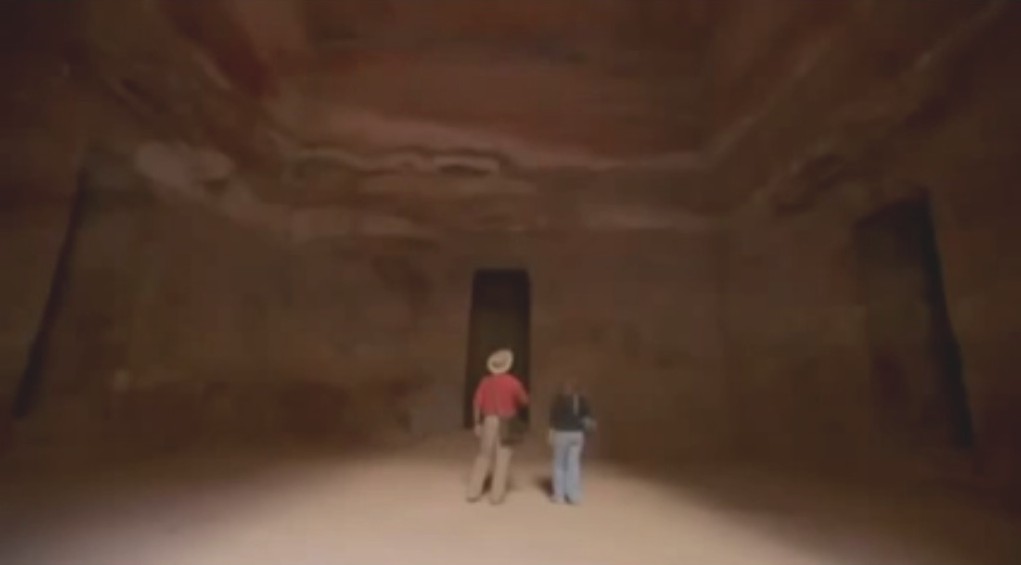
PETRA CAVITY ROOM 3DOORS IN CHAMBER AND SHAPE JUST FROM MAIN DOOR RIGHT CORNER. WHAT WAS PURPOSE FOR THIS SHAPE?

PETRA CAVITY ROOM LEFT PART FROM FRONT DOOR ENTRANCE/EXIT

PETRA CAVITY ROOM INSIDE LEFT CHAMBER DOOR SHAPE


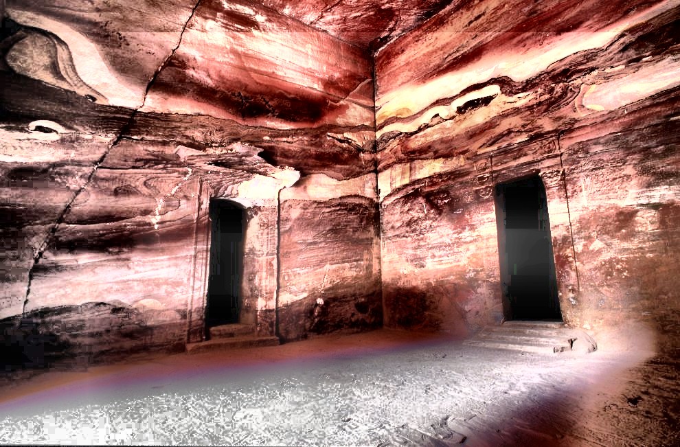
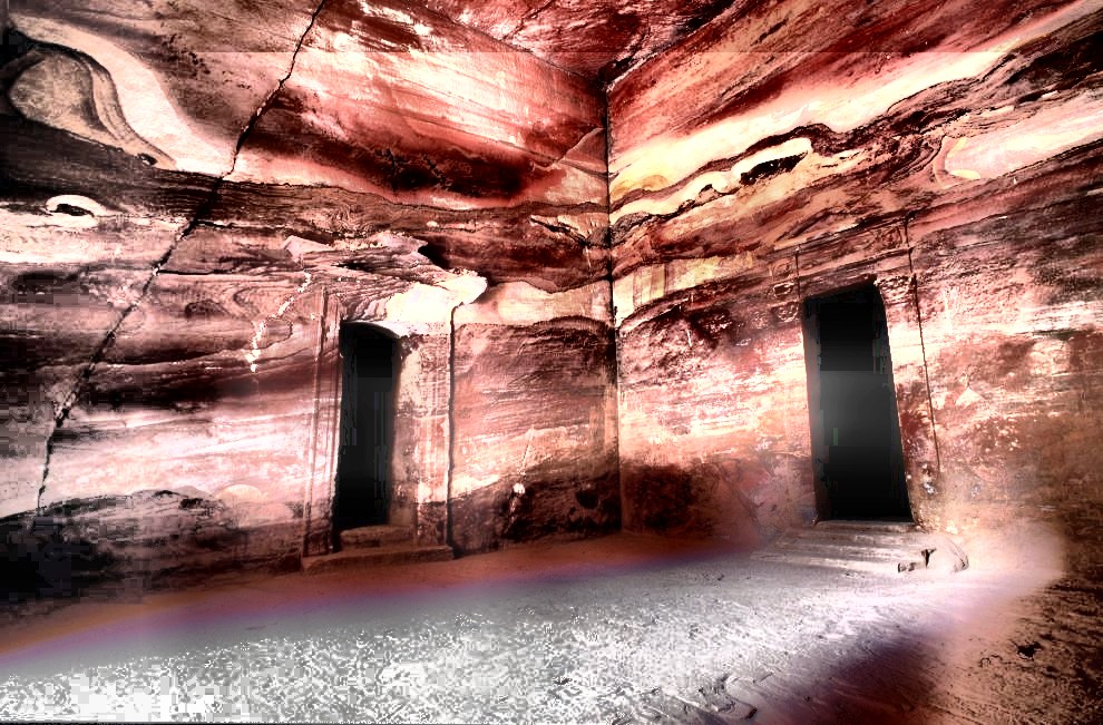
VISIBLE DIFFERENT IMAGES ON WALLS USING EQUALISATION PROCESS IN COREL PHOTO PAINT.
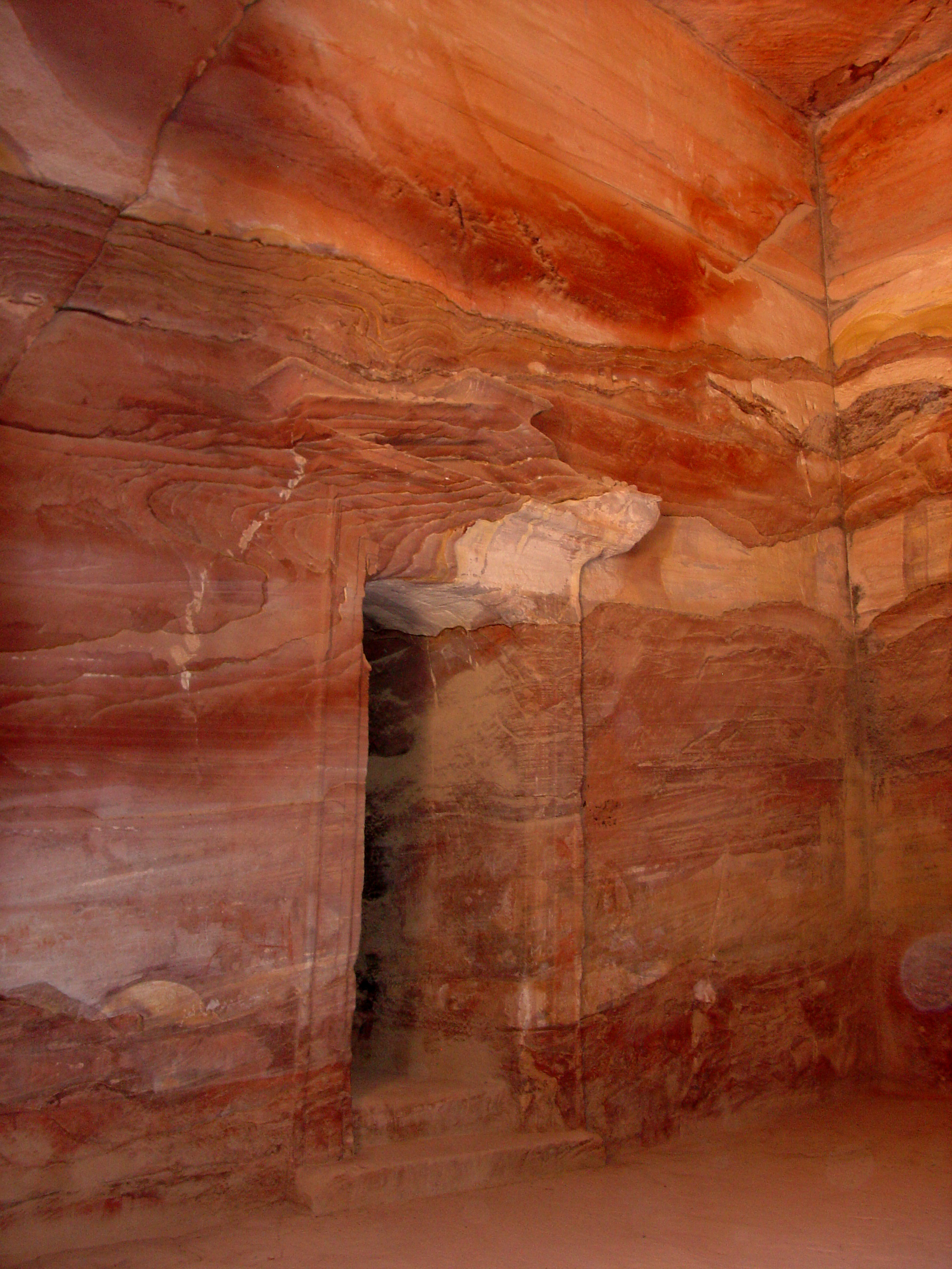
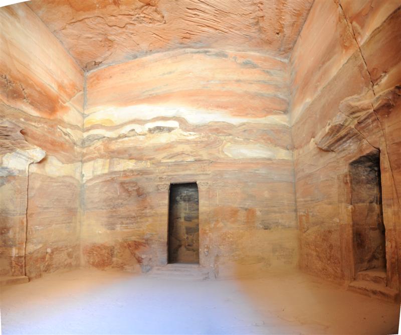
PETRA CAVITY ROOM AS RESONANT CHAMBER
LEFT DOOR AS RESONANT CHAMBER V2L CENTARL RESONANT CHAMBER DOOR
CENTRAL DOOR AS RESONANT CHAMBER V1
RIGHT DOOR DOOR AS RESONANT CHAMBER V2R

PETRA CAVITY ROOM AS RESONANT CHAMBER VISIBLE CEILING
Below is is internal drawing for cavity (sound) resonator rooms in PETRA.
Shape looks to me as microstrip microwave antenna, but huge.
All space-rooms is empty. What was inside in ancient time nobody know.
But if use present knowledge I am coming near solution what was purpose of PETRA....
Please, what you see when looking in those drawings.
What I discover is a simple huge cubical cut out of solid rock, with three small ante-chambers and I will discover the clues that may lead us to unraveling the so called Mystery of the Treasury Monument.
LISTEN SOUND FROM THE SKY AUDIO
| Sound oscillators running on air flows. | Звуковые генераторы на воздушных потоках. |
| The oscillator must efficiently convert the
energy flow into the wave energy of medium. For this purpose it is intended. Sound oscillator running on air energy flow is very effective.
Natural: B. Vocal apparatus of a whale. Created by human:
B. Whistle. C. Pyramidal infrasound oscillators. All oscillators, transmitters and receivers operate on the same principles which are
based on the resonance properties of the objects and wave energy transfer method. |
Генератор должен
эффективно превращать энергетический поток в
волновую энергию среды. Для этого он и предназначен. Звуковые генераторы работающие на воздушном энергетическом потоке весьма эффективны. Начнём с самых древних: 1. Голосовой аппарат человека. Представляет из себя многомодовый генератор звуковых волн, работающий на энергии сжатого воздуха. Имеет несколько резонаторов - голосовых связок (85..255 Гц). Входит в состав передатчика (глотка, язык, ротовая полость, зубы, губы) способного модулировать несущие звуковые частоты обертонами. Используется человеком для широковещательного обмена информацией в упругой среде через интерфейс "голос-слух". Весьма эффективен и универсален. Обеспечивает дальность связи до сотен метров в воздухе. 2. Голосовой аппарат кита. Способен генерировать инфразвуковые частоты в районе 18-30 Гц. Весьма эффективен. Обеспечивает наибольшую дальность передачи сигнала в воде до 1300км. Созданные человеком: 1. Духовые музыкальные инструменты. (Флейта, труба, валторна и др.) Звуковой генератор работающий на энергии воздушного потока. Имеет несколько встроенных резонаторов на разные частоты. Имеет модуляторы обертонов и элементы усиления амплитуды сигнала. 2. Свисток Простейший звуковой генератор на энергии воздушного потока. 3. Пирамидальные инфразвуковые генераторы. Описание этих звуковых генераторов см. PIRAMIDA Все генераторы, передатчики и приёмники работают по общим принципам. В основе которых лежат резонансные свойства объектов и передача энергии волновым способом. Поэтому работу этих устройств лучше всего можно объяснить на электрических устройствах. Так как современная цивилизация здесь сильно преуспела. |
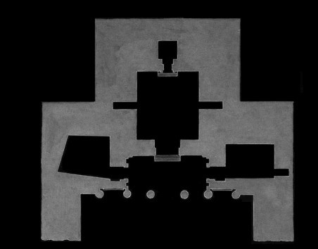
The layout of the rooms Treasury Monument is quite simple.
Floor plan of the Treasury Monument.

Aleksander Kushelev wrote: Rudolf find important information: It is fragment of electromagnetic generator in Petra megalithic complex.
Shape looks to me as microstrip microwave antenna, but huge.


As the diagram below illustrates, there are three main chambers: one very large central one, and two smaller ones right and left of the porch. The main central chamber had a rear-back chamber plus two side niches. The chamber to the right of the porch also has a large back niche.


PETRA MAIN ROOM IS AS: RESONATOR DRAWING FOR 4GHz FREQUENCY DESIGN BY ALEKSANDER KUSHLEV.
Floor plan of the Treasury Monument.
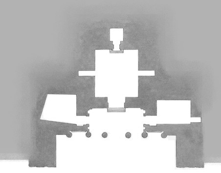
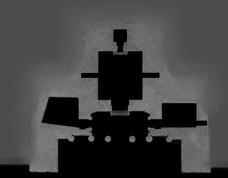
Aleksander Kushelev wrote: Rudolf find important information: It is fragment of electromagnetic generator in Petra megalithic complex.
Shape looks to me as microstrip microwave antenna, but huge.


Aleksander Kushelev wrote: Rudolf find important information: It is fragment of electromagnetic generator in Petra megalithic complex.
Shape looks to me as microstrip microwave antenna, but huge.
Prava kopiranja ©. 2015. Sva prava pridržana. Rudolf Bošnjak. Copyright ©. 2015 All rights reserved. Rudolf (Boschnjak) Bosnjak.

Prava kopiranja ©. 2015. Sva prava pridržana. Rudolf Bošnjak. Copyright ©. 2015 All rights reserved. Rudolf (Boschnjak) Bosnjak.
HERE is visible my hand drawing view of internal PETRA cavity cube rooms in blue color with cavity circle in orange color and in green color HORN ANTENNA for INPUT/EXIT waves (this is option) between tunnel and PETRA cavity cube rooms (resonant chamber).
Prava kopiranja ©. 2015. Sva prava pridržana. Rudolf Bošnjak. Copyright ©. 2015 All rights reserved. Rudolf (Boschnjak) Bosnjak.
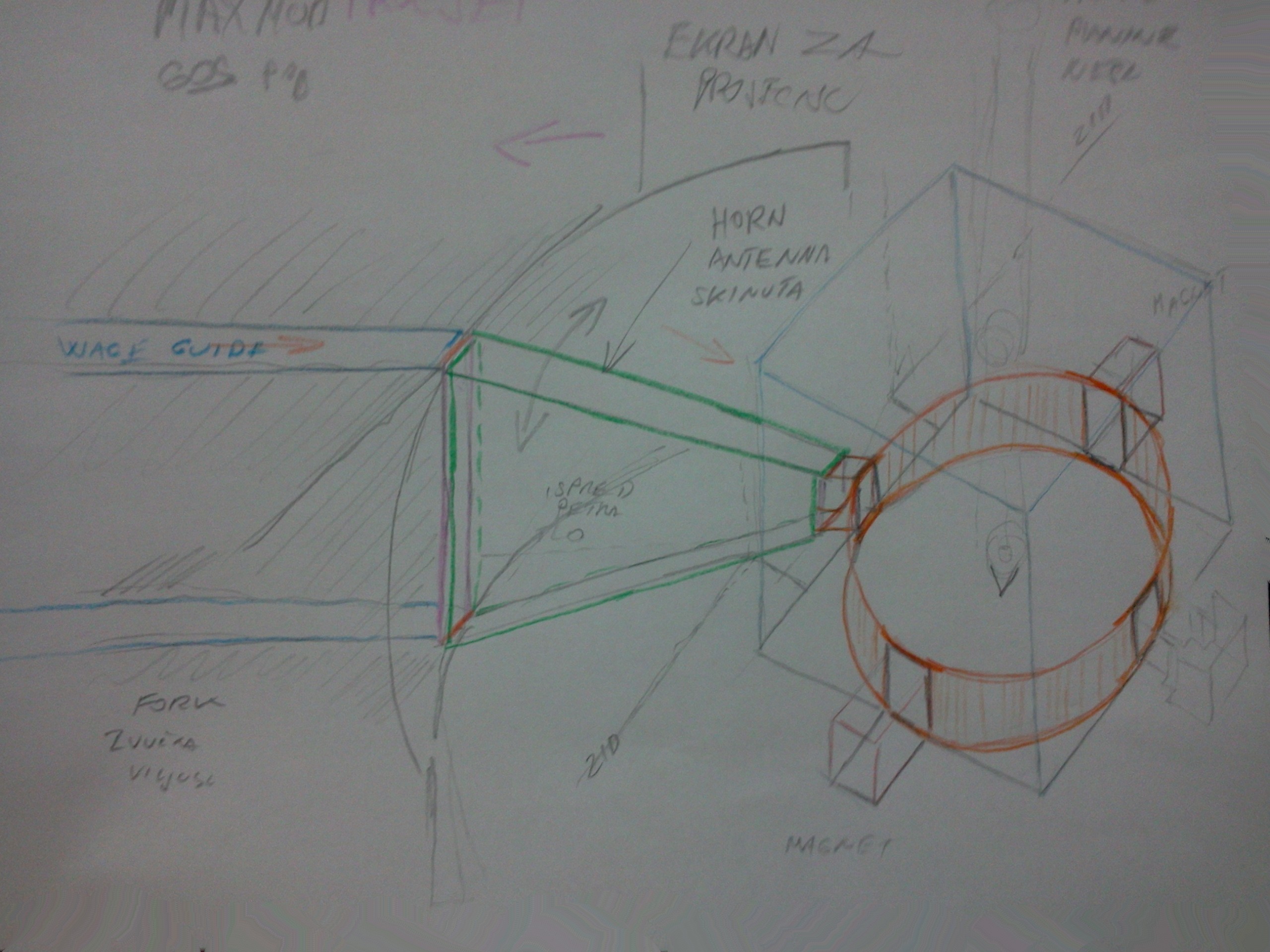
PETRA - RESONANT CAVITY MAGNETRON FIRST HAND DRAWING DIAGRAM
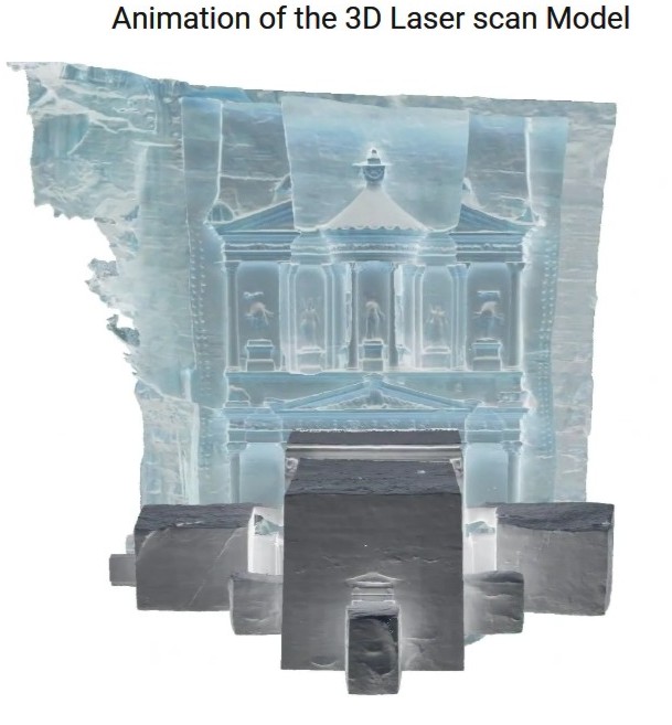
Prava kopiranja ©. 2015. Sva prava pridržana. Rudolf Bošnjak. Copyright ©. 2015 All rights reserved. Rudolf (Boschnjak) Bosnjak.
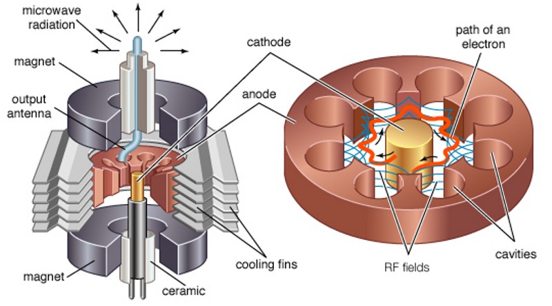
PETRA - RESONANT CAVITY MAGNETRON DIAGRAM

Image below show visible PETRA VERTICAL tunnel to PETRA cavity cube rooms or resonant chamber.
Prava kopiranja ©. 2015. Sva prava pridržana. Rudolf Bošnjak. Copyright ©. 2015 All rights reserved. Rudolf (Boschnjak) Bosnjak.
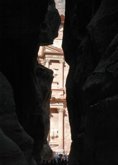
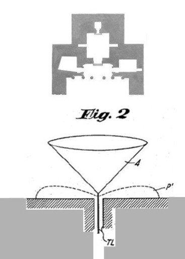
PETRA CAVITY ROOM AND view from VERTICAL tunnel to the resonant chamber. See in below image mark with TL same thing.

I call VERTICAL tunnel to the resonant chamber mark in Figure 2 with TL in Carter’s conical monopole (right)
Prava kopiranja ©. 2015. Sva prava pridržana. Rudolf Bošnjak. Copyright ©. 2015 All rights reserved. Rudolf (Boschnjak) Bosnjak.
Image below show visible VERTICAL slit tunnel...
From this tunnel was comming wire mark with TL in above image Figure 2.
Prava kopiranja ©. 2015. Sva prava pridržana. Rudolf Bošnjak. Copyright ©. 2015 All rights reserved. Rudolf (Boschnjak) Bosnjak.
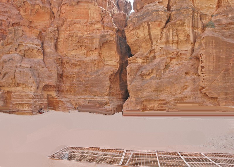
View from PETRA CAVITY ROOM as resonant chamber to the tunnel and missing parts is FRAME FOR 1 SOUND inside tunnel.
Prava kopiranja ©. 2015. Sva prava pridržana. Rudolf Bošnjak. Copyright ©. 2015 All rights reserved. Rudolf (Boschnjak) Bosnjak.
Prava kopiranja ©. 2015. Sva prava pridržana. Rudolf Bošnjak. Copyright ©. 2015 All rights reserved. Rudolf (Boschnjak) Bosnjak.
Image below is visible as my hand drawing view PETRA VERTICAL tunnel to PETRA cavity cube rooms or resonant chamber.
Prava kopiranja ©. 2015. Sva prava pridržana. Rudolf Bošnjak. Copyright ©. 2015 All rights reserved. Rudolf (Boschnjak) Bosnjak.
From this tunnel was comming wire mark with TL in above image Figure 2.
I call VERTICAL tunnel to the resonant chamber mark in Figure 2 with TL in Carter’s conical monopole (right) which radiate waves in conical shape to the front PETRA MAIN VERANDAH PILLARS delay line meander.


Now, bottom of this images SHAPE is shown IN HINDU VEDA AS VEDIC MOUNT MERU...
From this tunnel was comming wire mark with TL in above image Figure 2.
PETRA CAVITY ROOM AND VERTICAL TUNNEL FROM ABOVE

SHAPE is shown IN HINDU VEDA AS VEDIC MOUNT MERU...
Prava kopiranja ©. 2015. Sva prava pridržana. Rudolf Bošnjak. Copyright ©. 2015 All rights reserved. Rudolf (Boschnjak) Bosnjak.
Speed of Sound in Air in PETRA CAVITY ROOMS
The speed of sound in dry air is given approximately by

for temperatures reasonably close to room temperaature, where TC is the celsius temperature,
This calculation is usually accurate enough for dry air, but for great precision one must examine the more general relationship for sound speed in gases. If you measured sound speed in your oven, you would find that this relationship doesn't fit. At 200°C this relationship gives 453 m/s while the more accurate formula gives 436 m/s. This sound speed does not apply to gases other than air, for example the helium from a balloon.
It is important to note that the sound speed in air is determined by the air itself. It is not dependent upon the sound amplitude, frequency or wavelength.
Sound Propagation in PETRA CAVITY ROOMS
Sound propagates through air as a longitudinal wave. The speed of sound is determined by the properties of the air, and not by the frequency or amplitude of the sound. Sound waves, as well as most other types of waves, can be described in terms of the following basic wave phenomena.
Interference of Sound in PETRA CAVITY ROOMS
Two traveling waves which exist in the same medium will interfere with each other. If their amplitudes add, the interference is said to be constructive interference, and destructive interference if they are "out of phase" and subtract. Patterns of destructive and constructive interference may lead to "dead spots" and "live spots" in auditorium acoustics.
Interference of incident and reflected waves is essential to the production of resonant standing waves.
Interference has far reaching consequences in sound because of the production of "beats" between two frequencies which interfere with each other.
Standing Waves in PETRA CAVITY ROOMS
The term standing wave is often applied to a resonant mode of an extended vibrating object. The resonance is created by constructive interference of two waves which travel in opposite directions in the medium, but the visual effect is that of an entire system moving in simple harmonic motion. The sketches illustrate the fundamental and second harmonic standing waves for a stretched string.
The modes of vibration associated with resonance in extended objects like strings and air columns have characteristic patterns called standing waves. These standing wave modes arise from the combination of reflection and interference such that the reflected waves interfere constructively with the incident waves. An important part of the condition for this constructive interference for stretched strings is the fact that the waves change phase upon reflection from a fixed end. Under these conditions, the medium appears to vibrate in segments or regions and the fact that these vibrations are made up of traveling waves is not apparent - hence the term "standing wave".
I send e-mail to Jordan Museum asking them to send me all dimension inside with all spaces and rooms inside and from main entrance and dimension of columns and spaces between them. I hope I will get answer.
Prava kopiranja
©. 2015. Sva prava pridržana. Rudolf Bošnjak.
Copyright ©. 2015 All rights reserved.
Rudolf (Boschnjak) Bosnjak.
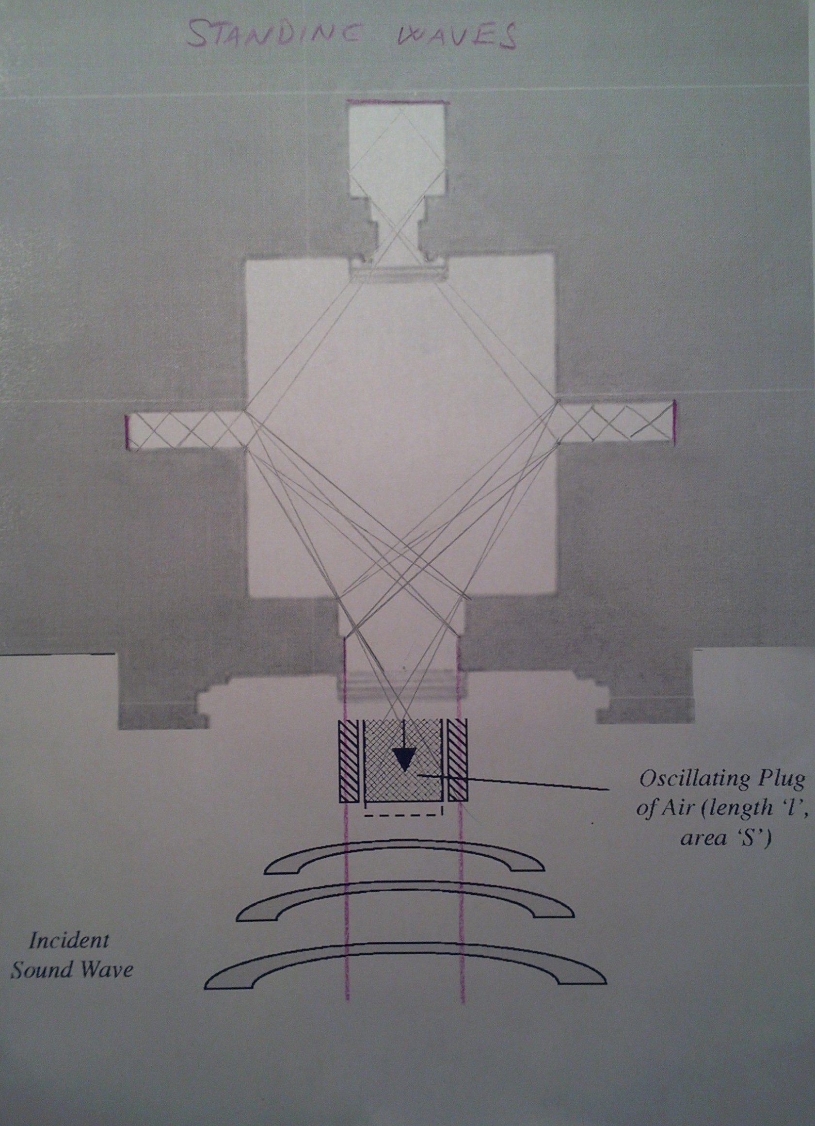
Prava kopiranja ©. 2015. Sva prava pridržana. Rudolf Bošnjak. Copyright ©. 2015 All rights reserved. Rudolf (Boschnjak) Bosnjak.
PETRA CAVITY ROOMS WAVE: PROPAGATION, RESONANCE, STANDING WAVES, STRINGS, AIR COLUMN, REFLECTIONS, REFRACTION, DIFFRACTION, SOUND REPRODUCTIONS and lot more.
The behavior of the waves at the points of minimum and maximum vibrations (nodes and antinodes) contributes to the constructive interference which forms the resonant standing waves. The illustration above involves the transverse waves on a string, but standing waves also occur with the longitudinal waves in an air column. Standing waves in air columns also form nodes and antinodes, but the phase changes involved must be separately examined for the case of air columns.
Prava kopiranja ©. 2015. Sva prava pridržana. Rudolf Bošnjak. Copyright ©. 2015 All rights reserved. Rudolf (Boschnjak) Bosnjak.

Prava kopiranja ©. 2015. Sva prava pridržana. Rudolf Bošnjak. Copyright ©. 2015 All rights reserved. Rudolf (Boschnjak) Bosnjak.
PETRA CAVITY ROOM VOLUME 1 FROM ABOVE
Displacement and Pressure in PETRA CAVITY ROOMS
The standing waves associated with resonance in air columns have been discussed mainly in terms of the displacement of air in the columns. They can also be visualized in terms of the pressure variations in the column. A node for displacement is always an antinode for pressure and vice versa, as illustrated below. When the air is constrained to a node, the air motion will be alternately squeezing toward that point and expanding away from it, causing the pressure variation to be at a maximum. This view of resonant modes in terms of pressure waves makes it easier to see why the mouthpiece end of a wind instrument is a node for the resonances. For example, the clarinet is acoustically a closed-end cylindrical air column because the mouthpiece end acts as a pressure antinode. An oboe is induced to produce its upper register by opening a hole near the mouthpiece, releasing pressure to make that point a pressure node and therefore a displacement antinode.
Prava kopiranja ©. 2015. Sva prava pridržana. Rudolf Bošnjak. Copyright ©. 2015 All rights reserved. Rudolf (Boschnjak) Bosnjak.
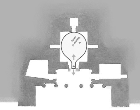
Prava kopiranja ©. 2015. Sva prava pridržana. Rudolf Bošnjak. Copyright ©. 2015 All rights reserved. Rudolf (Boschnjak) Bosnjak.
PETRA CAVITY ROOM VOLUME 2 FROM ABOVE
Anode block magnetron energy converter from below is very simailar to my hand drawing above but it is not same, just similar, now when I know what is what I can go further in my reserch.
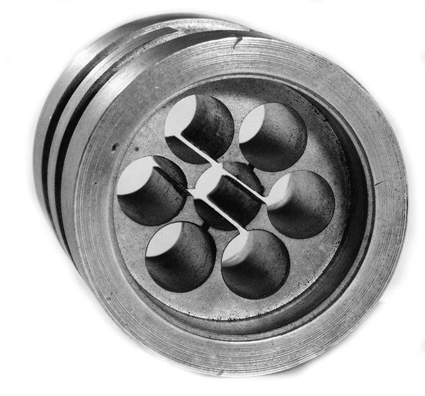
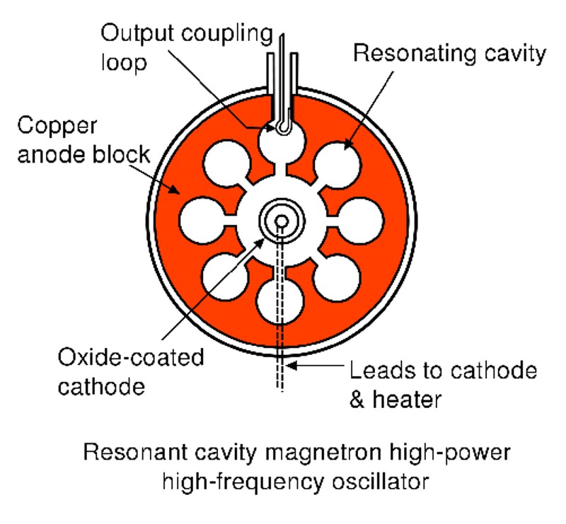
LEFT IS: ORIGINAL CAVITY MAGNETRON DEVELOPED 1940 YEAR.
This is called the Anode Block Cavity Magnetron energy converter and probably this device was in space I call V1 or resonant chamber and in my research I use sound waves for easy explanation for reflection in PETRA VERANDAH MEANDER SPACE, remember this is similar only in this part of my research.
Pressure and Displacement, Air Column in PETRA CAVITY ROOMS
The standing waves associated with resonance in air columns have been discussed mainly in terms of the displacement of air in the columns. They can also be visualized in terms of the pressure variations in the column. A node for displacement is always an antinode for pressure and vice versa, as illustrated below. When the air is constrained to a node, the air motion will be alternately squeezing toward that point and expanding away from it, causing the pressure variation to be at a maximum. This view of resonant modes in terms of pressure waves makes it easier to see why the mouthpiece end of a wind instrument is a node for the resonances. For example, the clarinet is acoustically a closed-end cylindrical air column because the mouthpiece end acts as a pressure antinode.
Prava kopiranja ©. 2015. Sva prava pridržana. Rudolf Bošnjak. Copyright ©. 2015 All rights reserved. Rudolf (Boschnjak) Bosnjak.
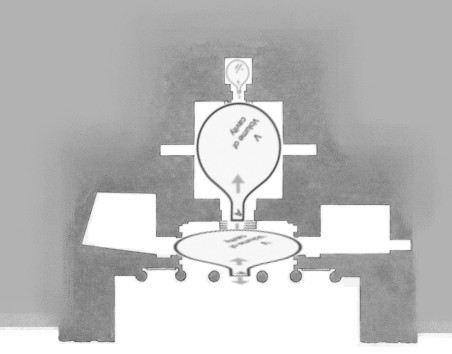
PETRA CAVITY ROOM VOLUME 1, VOLUME 2, VOLUME 3 FROM ABOVE
Prava kopiranja ©. 2015. Sva prava pridržana. Rudolf Bošnjak. Copyright ©. 2015 All rights reserved. Rudolf (Boschnjak) Bosnjak.
PETRA - THIS IS MAIN VERANDAH ENTRANCE, LEFT and RIGHT SIDE.
There is doors to left side room space I call V4 and dooors to right side room I call V5.
PETRA CAVITY ROOM FROM VERANDAH

PETRA - RESONANT CAVITY MAGNETRON DIAGRAM AND VISIBLE ROOM SPACE V2L and V2R.
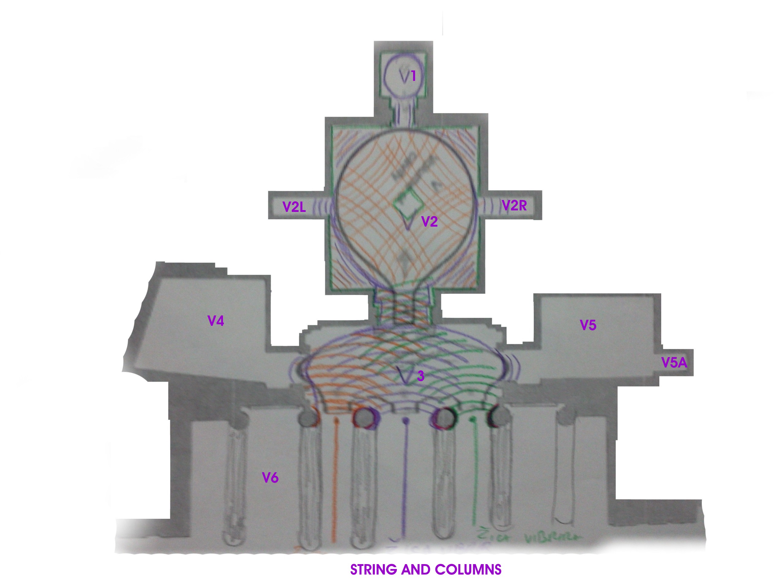
Below is visible my hand drawing view from above of internal PETRA cavity cube rooms and possible reflection, possible resonance, possible diffraction and possible amplification and lot more complex waves which appear between so many spaces inside...
Prava kopiranja ©. 2015. Sva prava pridržana. Rudolf Bošnjak. Copyright ©. 2015 All rights reserved. Rudolf (Boschnjak) Bosnjak.
PETRA CAVITY ROOMS VOLUME 1, VOLUME 2, VOLUME 2Left, VOLUME 2Right, VOLUME 3, VOLUME 4, VOLUME 5, VOLUME 5A, VOLUME 6 FROM ABOVE.
As is visible from my personal drawings, WHICH IS NOT FINISHED YET, PETRA CAVITY ROOMS is very complex system for kind of waves: RECEIVING or TRANSMITTING or GENERATING or PRODUCING SOMETHING, AND WITH HUMAN PRESENT KNOWLEDGE AND WHAT I FOUND LOOKS LIKE ALL THIS Rx, Tx, Generator SYSTEMS ARE EMBEDDED IN PETRA ROOMS...and all parts from inside and outside are dismantled in very distant parts and are gone...Most important: THIS IS NOT TOMB AS ARCHEOLOGIST CLAIMS for years.
PILLARS IN FRONT OF PETRA CAVITY RESONANCE ROOM
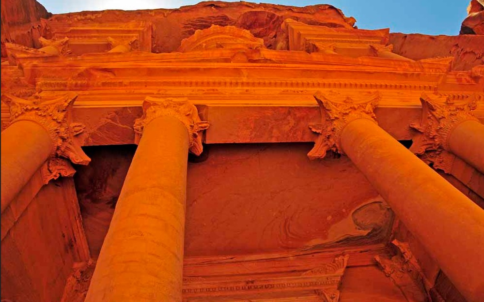
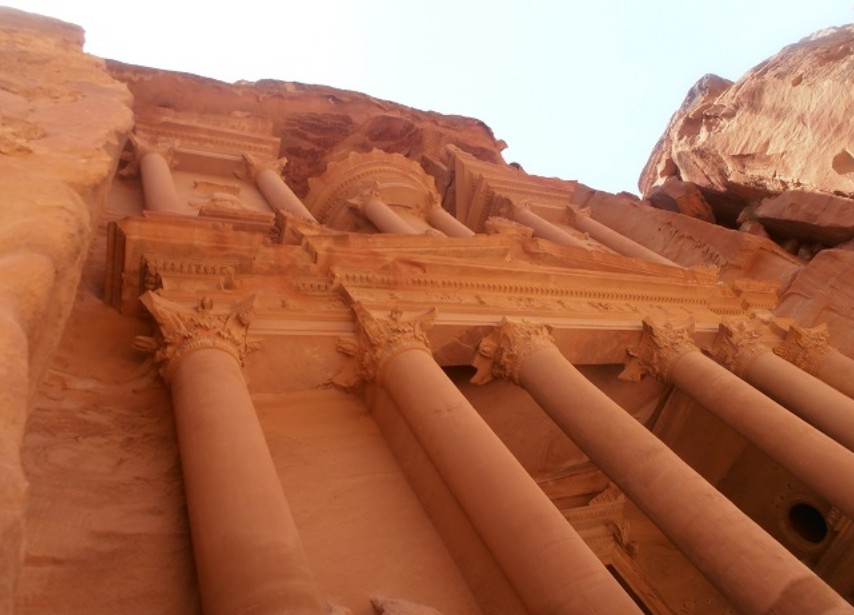
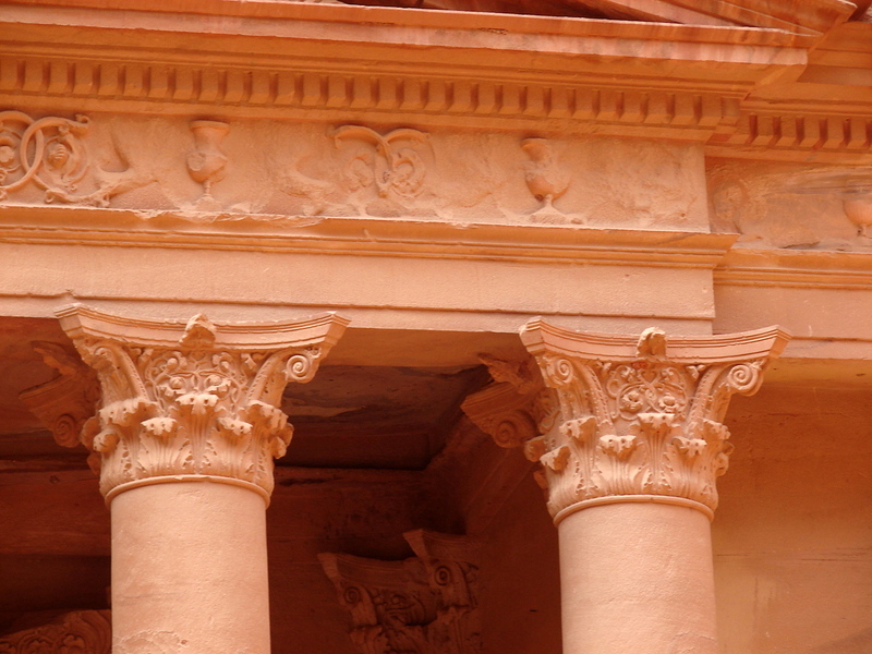
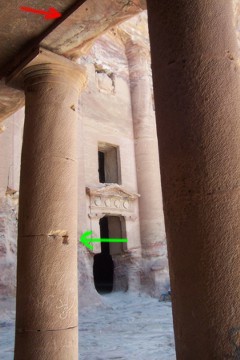
I MARK WITH RED ARROW WHERE WAS TOP REMOVED FRAME FOR STRING WIRE AND WITH GREEN ARROW WHERE WAS MIDDLE SUPPORT REMOVED FRAME FOR STRING WIRE BETWEEN PILLARS.
String Properties - Where string or strings are installed in PETRA CAVITY ROOMS
The vibration of the strings on stringed instruments have the form of standing waves which produce a fundamental frequency and all harmonics of that fundamental frequency simultaneously. These frequencies depend upon the tension, mass and length of the string. The harmonics make the sound timbre fuller and richer than the fundamental alone. The particular mix of harmonics present depends upon the method of excitation of the string.
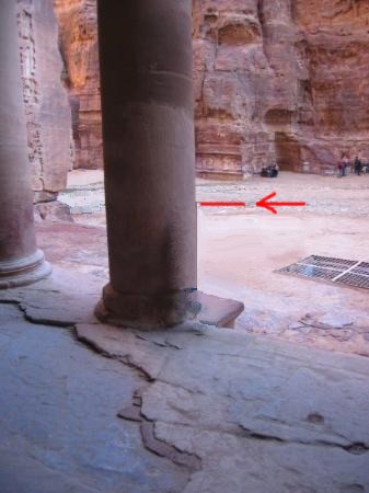
PILLARS IN FRONT OF PETRA CAVITY RESONANCE ROOM I MARK WITH RED LINE AND RED ARROW HEIGHT OF AVERAGE HUMAN.
B. Whistle.
It is the simplest audio oscillator that runs on energy of the air
flow.
OUR EARTH SCIENTIST KNOW FOR 2 SLIT SOUND EXPERIMENT
AND IN PETRA IS WORKING MODEL WITH 3 SLIT SOUND EXPERIMENT
Prava kopiranja ©. 2015. Sva prava pridržana. Rudolf Bošnjak. Copyright ©. 2015 All rights reserved. Rudolf (Boschnjak) Bosnjak.

Prava kopiranja ©. 2015. Sva prava pridržana. Rudolf Bošnjak. Copyright ©. 2015 All rights reserved. Rudolf (Boschnjak) Bosnjak.
PETRA CAVITY ROOM FROM ABOVE WHERE 1 SOUND FREQUENCY ARRIVE FROM RESONANT TUNNEL SLIT IN SPACE V6 FROM STONE ROCK OPPOSITE TO THE FRONT COLUMNS,

VIEW FROM WHERE 1 SOUND FREQUENCY ARRIVE FROM RESONANT TUNNEL TO THE PETRA CAVITY ROOM PILLARS.
AND BETWEEN EACH OF 2 COLUMNS WAS IN DISTANT PAST KIND OF WHISTLE STRING OR WIRE I MARK THEM WITH THIS COLORS: ORANGE, PINK and GREEN
AND THIS 3 SLIT PRODUCE EACH OF THEM WITH 1 SOUND FREQUENCY WHICH ARRIVE FROM RESONANT TUNNEL AND PRODUCE FOLLOWING:
1 - ORANGE DTMF (Dual Tone Multifrequency) SOUND,
2 - PINK DTMF (Dual Tone Multifrequency) SOUND and
3 - GREEN DTMF (Dual Tone Multifrequency) SOUND,
AND NOW ALL THOSE 3 MIX DTMF SOUNDS ENTRY INTO
PETRA RESONANT CHAMBER IN: VOLUME 2, VOLUME 3, VOLUME 4, VOLUME 5, VOLUME 5A....
IMPORTANT TO UNDERSTAND: What I call WHISTLE STRING OR WIRE, COULD BE ANY SOURCE OF VIBRATION or FREQUENCY with MODULATION...
This is very, very complex and complicating system for explanation for kind of vibration of incoming and outgoing (sound) or other waves and interference between all of them...
Wave lenght - Frequency
1 meter - 300 MHz - 300 MHz Oscillators Using SAW Resonators and Delay Lines or PILLARS DELAY LINE (meander).
100-300 MHz Frequency Range Wave Resonator
10 meters - 30 MHz
30 meters - 10 MHz
100 meters - 3 MHz
Room size = ~0.5 wave lengh
Air Column Instruments - Where column instruments are installed in PETRA CAVITY ROOMS
The woodwind instruments use only the first few resonances of air columns and depend upon opening holes in the sides of the air columns to ascend in pitch. The brass instruments employ a large number of resonances (harmonics) of their air columns and make use of valves or slides to lengthen the air columns for a downward progression of pitches.
Air Column Excitation in PETRA CAVITY ROOMS
While the frequencies produced by an air column instrument depend upon the type of column, the timbre of the sound is significantly influenced by the method of excitation of the air column. The flute and the recorder, as well as diapason organ pipes, are excited by blowing air over an edge. This edgetone can be altered by changing airstream velocity or the distance between slit and edge, so that an upper register is possible.
Other woodwinds may use a single reed (clarinet, saxophone) or a double reed (oboe, bassoon) to excite the air column. Such instruments achieve their upper register with the use of a register key which destroys the lowest mode of vibration of the air column and forces the column to vibrate at its next highest harmonic. For the clarinet this upper register is the third harmonic, but for the other woodwinds, it is an octave up because they are conical air columns.
Air Column Registers in PETRA CAVITY ROOMS
The playing range of woodwind instruments is extended by the existence of upper registers which allow them to excite upper harmonics of the air columns. In the flute the process is called overblowing. The upper register is an octave up in such instruments since they act as open-ended cylinders.
Other woodwinds achieve their upper register with the use of a register key which destroys the lowest mode of vibration of the air column and forces the column to vibrate at its next highest harmonic. For the clarinet this upper register is the third harmonic, but for the other woodwinds, it is an octave up because they are conical air columns.
PETRA ROOMS BELOW MAIN CAVITY ROOMS

To be continued...
Aleksander Kushelev wrote: Rudolf find important information: It is fragment of electromagnetic generator in Petra megalithic complex.
Regards Rudolf Bosnjak
Prava kopiranja ©. 2015. Sva prava pridržana. Rudolf Bošnjak. Copyright ©. 2015 All rights reserved. Rudolf (Boschnjak) Bosnjak. |
|