|
ELECTROMAGNETIC MODELING AS DRAWING MODELS IN ANCIENT TIME
Discovery by Rudolf Bosnjak
To comprehend and understand my research work and my research explanations and my drawings you must be sound engineer or electronic engineer not archeologist. Explanations here are totally opposite from science of archeology.
PRESENT MODELING OF MAGNETIC FIELD FLOW IN GREEN LINES AND SAME ANCIENT TIME DAVID STAR MODELING MAGNETIC FIELD FLOW IN GREEN LINES.
Prava kopiranja ©. 2015. Sva prava pridržana. Rudolf Bošnjak. Copyright ©. 2015 All rights reserved. Rudolf (Boschnjak) Bosnjak.
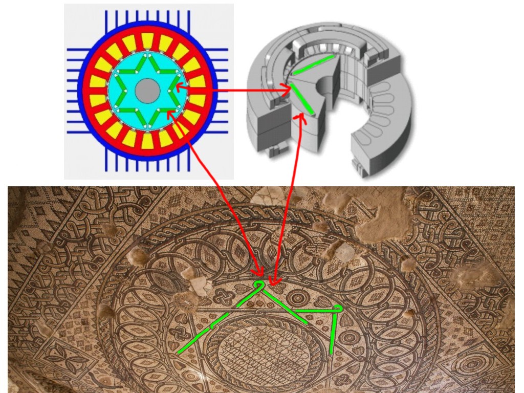
PRESENT MODELING OF MAGNETIC FIELD FLOW IN GREEN LINES AND SAME ANCIENT TIME DAVID STAR MODELING MAGNETIC FIELD FLOW IN GREEN LINES.
ELECTROMAGNETIC MODELING AS DRAWINGS MODELS IN ANCIENT TIME In ancient time much more before Hindu, Jews, Egypt, Greek and Roman civilization, they know also terms we use today: electromagnetic performance of motors and generators and the optimisation of their cooling and they knew about design modules for brushless permanent magnet machines (BPM), with inner and outer rotor configurations, and produce optimum designs for performance, energy efficiency, size and cost reduction and are modelled as electromagnetic performance tests that take into account the thermal aspects of the machine.
Prava kopiranja ©. 2015. Sva prava pridržana. Rudolf Bošnjak. Copyright ©. 2015 All rights reserved. Rudolf (Boschnjak) Bosnjak.

LEFT: COOPER WIRES PRESENT SOFTWARE SIMULATION MODELING and RIGHT: SAME MODELING IN ANCIENT TIME PRESENTED EVERY WHERE ON STECHAK AND MOSAIC AS GRAPE BUT THIS IS ACTUALLY 15 WIRES SHOWN.
HERE IS MY LONG AND HARD WORK IN DECIPHERING ANCIENT MOSAIC DRAWING WITH SOFTWARE SIMULATION PROGRAMS, I EXPLAIN TERMS AND DESCRIPTION FOR ELECTRIC MOTOR IN ANCIENT TIME and TERMS AND DESCRIPTION FOR ELECTRIC MOTOR IN PRESENT TIME
Prava kopiranja ©. 2015. Sva prava pridržana. Rudolf Bošnjak. Copyright ©. 2015 All rights reserved. Rudolf (Boschnjak) Bosnjak.
| TERMS AND DESCRIPTION FOR ELECTRIC MOTOR ANCIENT TIME |
TERMS AND DESCRIPTION FOR ELECTRIC MOTOR PRESENT TIME |
| Confirm requirements Select template Sizing An initial design proposal is made using the Sizing function. Confirm outer diameter and poles |
|
COOPER WIRES PRESENT MODELING SAME MODELING IN ANCIENT TIME |
Confirm winding Confirming the winding. The default setting is 1 mΩ. Set winding By selecting [Round Wire Dimension] under [Setting Type], the phase
resistance value and others can be evaluated while confirming the slot fill factor.
|
| Change dimensions Rounding off fractions in the dimensions. The Sizing function makes the geometry's dimensions by proportional calculation, and they tend to come out as complex fractions, so they are rounded to 0.5 mm increments. |
|
| Set drive conditions
Change materials Characteristics (plan A) Results (plan A) Confirm weight and inductance The total mass is found to be X kg. The market rate is 1 kW = 1 kg,
so if the target is reached, weight will not be a problem. Characteristics: phase angle advanced 45 deg (plan B) Analysis is done with the current phase set at 55 deg to see what
happens if it is advanced further. This design proposal is called Plan C. Compare results (plan B) Characteristics: phase angle advanced 45 deg (plan C) Narrow gap Differences in properties are confirmed when the air gap is varied. Characteristics (plan D) Widen gap The air gap is widened instead. Characteristics (plan E) Characteristics: current limit lowered (plan F) Reduce outer diameter The model's outside diameter is reduced from φ202 to φ192 for Plan G because a small weight reduction is desired. Characteristics (plan G) Reduce shaft diameter The shaft diameter is increased from φ41 to φ51. This design proposal is called Plan H. Characteristics (plan H) Plan H, with the inside rotor diameter increased, reduces the weight from X to Y kg. Similar to the stator, this is shown to have no effect on performance.
|
ELECTROMAGNETIC FORMING ANALYSIS OF A TUBE IN ANCIENT TIME Electromagnetic forming is a process in which Eddy currents are generated in a tube when a large, instantaneous current is run through a coil, creating a strong magnetic field. The tube is formed by using the Lorenz force produced by the interaction between these magnetic fields. The force generated in the tube is determined from induced Eddy currents, which means that it is dynamic deformation, so the behavior of its deformation is known for being difficult to analyze. Using some software programs we can to properly analyze the Lorenz force distribution generated in the tube can assist with predicting the deformation behavior of the electromagnetic forming process. How to obtain the Lorenz force density distribution generated in a tube when current is run through a coil. See my experiments here http://www.elektroauto.ba/ETM/index.html MAGNETIC SHIELDING ANALYSIS OF SHIELD ROOM IN ANCIENT TIME Shield rooms are meant to protect precision equipment from the influence of external magnetic fields, so they have to be an enclosed space that implements special processing in the walls that blocks magnetic flux. The effects of external magnetic fields inside the shield room depend on how they are generated, where the precision equipment is located, and the position of the shield room's opening and supply cable. A magnetic field analysis using the finite element method is necessary to perform an evaluation that deals with three dimensional and temporal variations to figure out how magnetic flux enters the shield room when several external magnetic fields have been applied.Explanations how to handle the magnetic shielding phenomena used by the shield room when an external magnetic field is applied, and from there how to confirm the magnetic flux density distribution. MAGNETIZATION ANALYSIS ACCOUNTING FOR EDDY CURRENTS IN ANCIENT TIME A magnet's magnetizing state largely affects the characteristics of a device that uses permanent magnets. A magnetization device performs magnetization by applying an extremely strong magnetic field to a magnet. The capacity of the magnetization power supply is also determined by multiplying the magnetization current by time. The production process requires that magnetization be performed by running a large current through a magnetization coil in an extremely short period of time. However, eddy currents are generated in the magnetic material to be magnetized when the currents time variations are too severe, opening the possibility that the intended magnetization distribution cannot be obtained. On the other hand, when the current changes too slowly the magnetizing device's capacity needs to be expanded, leading to an increase in production cost. This is why the trade-off between production costs and whether sufficient magnetization can be carried out needs to be studied. A magnetic field analysis using the finite element method (FEM) can handle the nonlinear magnetic properties of materials and eddy currents that are generated in the magnetic material to be magnetized when current flows through the coil. This makes it possible to discover how the magnetizing field will be generated and what effect it will have on the magnetization distribution. Presentation how to obtain the magnetization field distribution accounting for eddy currents in the magnetic material to be magnetized, the eddy current density distribution in the magnetic material to be magnetized, and the surface magnetic flux density of the magnet.
ANALYSIS OF COIL STRAY CAPACITANCE IN ANCIENT TIME In a high frequency application, not only the coil's inductance component but its capacitance component cannot be ignored and results in degradation of the circuit impedance characteristics and inconsistencies in resonance frequencies. Stray capacitance that occurs between the coil windings is one of them. For example, with a helical coil, electrical potential varies depending on its rotation so difference in electrical potential occurs between the neighboring windings. As a result, capacitance occurs between the windings and operates as a condenser component. The stray capacitance that occurs in the coil depends on its geometry. To obtain the stray capacitance that occurs in various types of coils, a magnetic analysis using FEM is effective. By modeling the entire coil, stray capacitance accounting for the distance between windings and differences in winding pattern can be obtained. Presenation on the helical coil, changes the distance between windings, and obtains stray capacitance that occurs in each coil.
Regards Rudolf Bosnjak
Prava kopiranja ©. 2015. Sva prava pridržana. Rudolf Bošnjak. Copyright ©. 2015 All rights reserved. Rudolf (Boschnjak) Bosnjak. |
www.bev.ba |
|